As we saw last time, the role of routers is to relay exchanges between different networks. The "different network" in this case refers to a network having a different network address. Of course, it also includes the one that was originally one network and was divided into subnets.
What happens when the number of routers increases?
By dividing the network, it is possible to prevent unnecessary packets such as broadcasts from spreading over a wide area. Subnetting is also effective from the viewpoint of security, such as when filtering by network. In companies and the like, measures such as making the network address different for each department or making it into a subnet are generally taken. The "Router" is located at the position where these subnets are put together. In the corporate network, it is common to use a "Layer 3 Switch" instead of a router, but the basic functions are the same. Therefore, the explanation will be given here using a router.
As the number of subnets increases, problems such as performance such as throughput and the number of physical ports occur, and one router cannot handle it. Also, as the size of the company grows and the number of bases increases, there are cases where one router cannot help.
Therefore, I would like to see what kind of settings are required and what is done when exchanging packets with a network connected to another router using two routers.
I will leave it to the other party for the time being
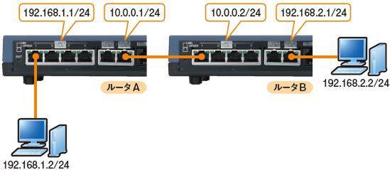
In this experiment, two routers (here, A and B) are directly connected, and one network is connected to each router. Each setting is as shown in Fig. 1.

Figure 1 This experimental environment using two Yamaha routers "RTX1100"
Assign 192.168.1.1/24 to the lan1 interface of Router A, and connect the 192.168.1.0/24 network (default gateway is 192.168.1.1) to it. Assign 192.168.2.1/24 to the lan3 interface of one router B, and connect it to the 192.168.2.0/24 network (default gateway is 192.168.2.1). The network connecting router A and router B is 10.0.0.0/24, 10.0.0.1 is assigned to the interface (lan3) on the router A side, and 10.0.0.2 is assigned to the interface (lan1) on the router B side.
The specific setting method is as shown in screen 1.
Screen 1 Subnet mask could be in cider notation or dot decimal notation
First, assign an IP address to each interface (lan1 or lan3), and then set the routing. If router A is used, packets destined for a network that is not connected to itself can be sent to router B, so router B is set to be the default gateway. Similarly, after setting the IP address for Router B, set Router A to be the default gateway. When the setting is completed, the routing table of Router A will be as shown in Screen 2.
Screen 2 Router A's routing table. static means static, implicit means "implicit"
With this done, I tried pinging and tracert from the PC connected to Router A (192.168.1.2) to the PC connected to Router B (192.168.2.2). The result is screen 3. You can see that the packet is properly delivered to the PCs on different networks via the two routers. The experiments so far have been successful.
Screen 3 As shown in the screen, it reaches the other party via two routers.
This article is a re-edited version of Feature 1 "Trial and Understanding Routing" in the November 2008 issue of Network Magazine. As a general rule, the content is as of the time of publication and may differ from the current one. |


